Car not starting.

benyeats

Re: Car not starting.

Post by benyeats » Mon May 19, 2014 9:07 pm

OK the results of this evening's tests.

i)  Monza, I assume you mean these connectors:

Image

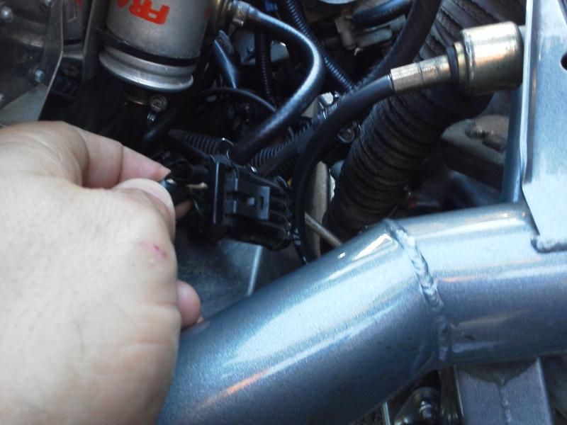
If so swapping them makes no difference, in fact afterwards I can no longer operate the fuel pump via the relay.

ii)  This is my test MFRU which has the cover removed so I can activate each relay by hand

Image

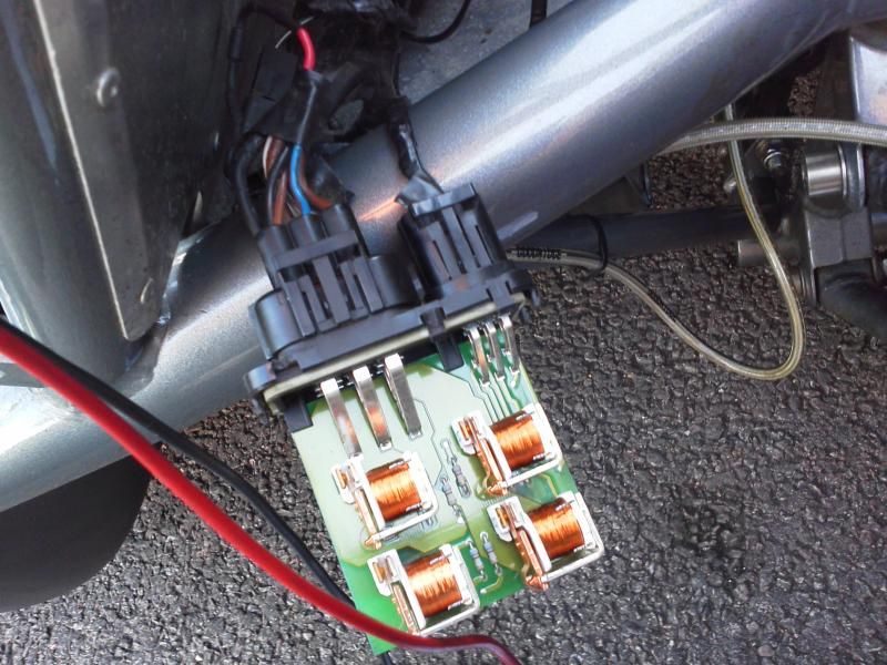
The upper right connection is the fuel pump relay, the lower right the 'master' relay, the lower left the starter relay.

The progress I have made this evening is pressing the master relay and the starter relay the car sounds like it is going to start, perhaps I have too little fuel in the tank to re-prime everything ( sub 5 litres) but it is almost running if I short those two contacts.

I can't find an electrical connection between the ECU pin 1 and the fuel pump relay, which is very likely the problem.

This is the Hondata pinout diagram I am using

Image

along with

http://www.k20a.org/forum/showthread.php?t=230 as backup.

Ben

benyeats

Re: Car not starting.

Post by benyeats » Mon May 19, 2014 9:44 pm

To add a bit more details, pins 1, 2 and 3 of this connector all have 12V on them.  Pin 2 this is OK as it is the 12V switched with the ignition for the fuel pump.  However 12V on pin 1 is a problem.  It must be coming from somewhere, just not the pin on the ECU which is at 0V as expected.

This leads me back to Monza's swapped connectors, but the fuel pump does not pump when those connectors are swapped and I short the relay.......ARGH


Image

benyeats

Re: Car not starting.

Post by benyeats » Tue May 20, 2014 7:03 pm

OK so a small confession to make.  I have tried to be too clever with this one. 

I opened the top of the ECU and was using the pin numbering showing on the PCB.  For some reason Honda then reverse this convention on the output of the plugs.  To be fair Honda's external numbering is logical, the numbering on the PCB is stupid.

Point being the fuel pump relay etc is no longer the problem.

What I am missing is the 12V ignition switch feed to the ECU, shorting this connection enabled me to almost start the car, suspect a bit more petrol is required.  Just need to trace this wire and see what is up........

Feels like I am nearly at the end......

Ben

meladdo

Re: Car not starting.

Post by meladdo » Tue May 20, 2014 7:32 pm

Is this pointing to the immobilizer again then?...I must confess Im a little lost in the story now.....

benyeats

Re: Car not starting.

Post by benyeats » Tue May 20, 2014 7:36 pm

[quote="meladdo"]
Is this pointing to the immobilizer again then?...I must confess Im a little lost in the story now.....
[/quote]

No I have the immobilizer jumped so it is out of the loop.

The problem now is the 12V feed to the ECU.  If I feed it directly then it all seems to work.  Broken wire somewhere I suspect.

Ben

meladdo

Re: Car not starting.

Post by meladdo » Tue May 20, 2014 7:48 pm

:tu:  And this is all after the engine out for the resent work Ben? could the loom have sustained an impact of gotten crushed as engine removed / replaced? or break in loom waiting to manifest itself as fault....

I had a fuel pump feed failure at speed on right lane of M6 in rush hour in the Caterham - not an experience I would like to repeat - fault on feed from MRFU to fuel pump bad connector spade had been arcing for a while and the heat under the bonnet is massive on the duratec 7ns

Hope you resolve it soon and you can take advantage of the sunshine

AtomMadStew

Re: Car not starting.

Post by AtomMadStew » Tue May 20, 2014 7:52 pm

A quick continuity check should give to your answer if you can successfully trace it Ben. I think you've found your problem

benyeats

Re: Car not starting.

Post by benyeats » Tue May 20, 2014 7:58 pm

[quote="Stew Bartley"]
A quick continuity check should give to your answer if you can successfully trace it Ben. I think you've found your problem
[/quote]

I have traced that there is no continuity between the ignition switch 12V and where it should be on the ECU ! 

Next step is to speak to the factory about which connectors the 12V feed to the ECU goes through so I can narrow down the location of the break.  Wish I had a wiring diagram......

[quote="meladdo"]
:tu:  And this is all after the engine out for the resent work Ben? could the loom have sustained an impact of gotten crushed as engine removed / replaced? or break in loom waiting to manifest itself as fault....
[/quote]

I think a connection must have got broken during the engine out work, just need to find out where.

Ben

AtomMadStew

Re: Car not starting.

Post by AtomMadStew » Tue May 20, 2014 9:15 pm

I have previously sold a Tool that locates breaks in wires wirelessly by connecting something to said broken wire and using a wireless reciever locates the break - rather than probing wiring at undetermined places . A Handy piece of kit in these situations I've heard - never used one though. Typically used on the French cars ;)

benyeats

Re: Car not starting.

Post by benyeats » Tue May 20, 2014 9:29 pm

[quote="Stew Bartley"]
I have previously sold a Tool that locates breaks in wires wirelessly by connecting something to said broken wire and using a wireless reciever locates the break - rather than probing wiring at undetermined places . A Handy piece of kit in these situations I've heard - never used one though. Typically used on the French cars ;)
[/quote]

I guess the 12V ignition signal goes something like

Ignition switch > isolator switch > body loom > ECU connection so the wire could be broken in one of four places.  My guess is between the ECU connection and the body loom.    Will find out pin outs from Ariel tomorrow.

Ben

User avatar
smokin
Posts: 1083
Joined: Sat Jul 24, 2010 6:33 pm
Contact:

Re: Car not starting.

Post by smokin » Wed May 21, 2014 3:11 am

ECM Inputs and Outputs at Connector A (31P)

Terminal number Wire colour Terminal name Description Signal
1 BLK/WHT PO2SHTC (PRIMARY HEATED OXYGEN SENSOR HEATER CONTROL) Drives primary HO2S heater With ignition switch ON (II): battery voltage With fully warmed up engine running: duty controlled
2 YEL/BLK IGP2 (POWER SOURCE) Power source for the ECM circuit With the ignition switch ON (II): battery voltage With the ignition switch OFF: about 0 V
3 YEL/BLK IGP1 (POWER SOURCE) Power source for the ECM circuit With the ignition switch ON (II): battery voltage With the ignition switch OFF: about 0 V
4 BLK PG2 (POWER GROUND) Ground for the ECM circuit Less than 1.0 V at all times
5 BLK PG1 (POWER GROUND) Ground for the ECM circuit Less than 1.0 V at all times
6 RED PHO2S (PRIMARY HEATED OXYGEN SENSOR, SENSOR 1) Detects primary HO2S sensor (sensor 1) signal With throttle fully opened from idle with fully warmed up engine: about 0.6 V With throttle quickly closed: below 0.4 V
7 BLU CKP (CRANKSHAFT POSITION SENSOR) Detects CKP sensor signal With engine running: pulses
9 RED/BLU KS (KNOCK SENSOR) Detects knock sensor signal With engine knocking: pulses
10 GRN/YEL SG2 (SENSOR GROUND) Sensor ground Less than 1.0 V at all times
11 GRN/WHT SG1 (SENSOR GROUND) Sensor ground Less than 1.0 V at all times
12 BLK/RED IACV (IDLE AIR CONTROL (IAC) VALVE) Drives IAC valve With engine running: duty controlled
15 RED/BLK TPS (THROTTLE POSITION SENSOR) Detects TP sensor signal With throttle fully open: about 4.8 V With throttle fully closed: about 0.5 V
18 WHT/GRN VSS (VEHICLE SPEED SENSOR) Detects VSS signal With ignition switch ON (II) and front wheels rotating: cycles about 0 V-about 5 V or battery voltage
19 GRN/RED MAP (MANIFOLD ABSOLUTE PRESSURE SENSOR) Detects MAP sensor signal With ignition switch ON (II): about 3 V At idle: about 1.0 V (depending on engine speed)
20 YEL/BLU VCC2 (SENSOR VOLTAGE) Provides sensor voltage With ignition switch ON (II): about 5 V With ignition switch OFF: about 0 V
21 YEL/RED VCC1 (SENSOR VOLTAGE) Provides sensor voltage With ignition switch ON (II): about 5 V With ignition switch OFF: about 0 V
23 BRN/YEL LG2 (LOGIC GROUND) Ground for the ECM circuit Less than 1.0 V at all times
24 BRN/YEL LG1 (LOGIC GROUND) Ground for the ECM circuit Less than 1.0 V at all times
25 BLU/WHT CMP (CAMSHAFT POSITION SENSOR) Detects CMP sensor signal With engine running: pulses
26 GRN TDC (TOP DEAD CENTRE SENSOR) Detects TDC sensor With engine running: pulses
27 BRN IGPLS4 (No.4 IGNITION COIL PULSE) Drives No.4 ignition coil With ignition switch ON (II): about 0 V With engine running: pulses
28 WHT/BLU IGPLS3 (No.3 IGNITION COIL PULSE) Drives No.3 ignition coil
29 BLU/RED IGPLS2 (No.2 IGNITION COIL PULSE) Drives No.2 ignition coil
30 YEL/GRN IGPLS1 (No.1 IGNITION COIL PULSE) Drives No.1 ignition coil
Attachments
11-12a38.gif
11-12a38.gif (5.47 KiB) Viewed 239 times
Atom 2 300, Ginetta G40 GT5 - UK

User avatar
smokin
Posts: 1083
Joined: Sat Jul 24, 2010 6:33 pm
Contact:

Re: Car not starting.

Post by smokin » Wed May 21, 2014 3:13 am

ECM Inputs and Outputs at Connector B (24P)

Terminal number Wire colour Terminal name Description Signal
1 BLU/WHT VTC+ (VTC OIL CONTROL SOLENOID VALVE +SIDE) Drives VTC oil control solenoid valve With ignition switch ON (II): 0 V
2 YEL INJ4 (No. 4 INJECTOR) Drives No. 4 injector At idle: duty controlled
3 BLU INJ3 (No. 3 INJECTOR) Drives No. 3 injector
4 RED INJ2 (No. 2 INJECTOR) Drives No. 2 injector
5 BRN INJ1 (No. 1 INJECTOR) Drives No. 1 injector
6 GRN FANC (RADIATOR FAN CONTROL) Drives radiator fan relay With radiator fan running: about 0 V With radiator fan stopped: battery voltage
7 GRN/WHT RVSLCK (REVERSE LOCKOUT SOLENOID VALVE) Drives reverse lockout solenoid valve. With vehicle speed above 20 km/h (12.5 mph): about 0 V With vehicle speed below 15 km/h (9.4 mph): battery voltage
8 RED/WHT ECT (ENGINE COOLANT TEMPERATURE SENSOR) Detects ECT sensor signal With the ignition switch ON (II): about 0.1 - 4.8 V (depending on engine coolant temperature)
9 BLU/BLK VTPSW (VTEC OIL PRESSURE SWITCH) Detects VTEC oil pressure switch signal With engine at low engine speed: about 0 V With engine at high engine speed: battery voltage
10 WHT/BLU ALTL (ALTERNATOR L SIGNAL) Detects alternator L signal With ignition switch ON (II): about 0 V With engine running: battery voltage
13 WHT/RED ALTF (ALTERNATOR FR SIGNAL) Detects alternator FR signal With engine running: about 0 V - 5 V (depending on electrical load)
15 GRN/YEL VTS (VTEC SOLENOID VALVE) Drives VTEC solenoid valve At idle: about 0 V
17 RED/YEL IAT (INTAKE AIR TEMPERATURE SENSOR) Detects IAT sensor signal With ignition switch ON (II): about 0.1 V - 4.8 V (depending on intake air temperature)
18 WHT/GRN ALTC (ALTERNATOR CONTROL) Sends alternator control signal With engine running: about 0 V - 5 V (depending on electrical load)
21 YEL/BLU PCS (EVAPORATIVE EMISSION CANISTER PURGE VALVE) Drives EVAP canister purge valve With engine running, engine coolant below 75°C (167°F): battery voltage With engine running, engine coolant above 75°C (167°F): duty controlled
23 BLK/WHT VTC- (VTC OIL CONTROL SOLENOID VALVE -SIDE) Drives VTC oil control solenoid valve With the ignition switch ON (II): 0 V
Attachments
11-12a38.gif
11-12a38.gif (3.79 KiB) Viewed 235 times
Atom 2 300, Ginetta G40 GT5 - UK

User avatar
smokin
Posts: 1083
Joined: Sat Jul 24, 2010 6:33 pm
Contact:

Re: Car not starting.

Post by smokin » Wed May 21, 2014 3:16 am

ECM Inputs and Outputs at Connector E (31P)

Terminal number Wire colour Terminal name Description Signal
1 GRN/YEL IMO FPR (IMMOBILISER FUEL PUMP RELAY) Drives PGM-FI main relay 2 0 V for two seconds after turning ignition switch ON (II), then battery voltage
2 WHT/RED SHO2S (SECONDARY HEATED OXYGEN SENSOR, SENSOR 2) Detects Secondary HO2S (sensor 2) signal With throttle fully opened from idle with fully warmed up engine: above 0.6 V With throttle quickly closed: below 0.4 V
3 BRN/YEL LG3 (LOGIC GROUND) Ground for the ECM/PCM control circuit Less than 1.0 V at all times
4 PNK SG3 (SENSOR GROUND) Sensor ground Less than 1.0 V at all times
6 BLK/WHT SO2SHTC (SECONDARY HEATED OXYGEN SENSOR HEATER CONTROL) Drives Secondary HO2S heater With ignition switch ON (II): battery voltage With fully warmed up engine running: duty controlled
7 RED/YEL MRLY (PGM-FI MAIN RELAY) Drives PGM-FI main relay 1 Power source for the DTC memory With ignition switch ON (II): battery voltage With ignition switch OFF: about 0 V
9 YEL/BLK IG1 (IGNITION SIGNAL) Detects ignition signal With ignition switch ON (II): battery voltage With ignition switch OFF: about 0 V
15 GRN/RED ELD (ELECTRICAL LOAD DETECTOR) Drives ELD signal With ignition switch ON (II): about 0.1 V - 4.8 V (depending on electrical load)
16 LT GRN/BLK EPSLD (ELECTRICAL POWER STEERING LOAD DETECT) Detects power steering load signal At idle steering wheel in straight ahead position: about 0 V At idle with steering wheel at full lock: battery voltage momentarily
18 RED ACC (A/C CLUTCH RELAY) Drives A/C clutch relay With compressor ON: about 0 V With compressor OFF: battery voltage
22 WHT/BLK BKSW (BRAKE PEDAL POSITION SWITCH) Detects BPP switch signal With brake pedal released: about 0 V With brake pedal pressed: battery voltage
23 LT BLU K-LINE Sends and receives scan tool signal With ignition switch ON (II): pulses or battery voltage
24 YEL SEFMJ Communicates with multiplex control unit With ignition switch ON (II): about 5 V With engine running with load: pulses
26 BLU NEP (ENGINE SPEED PULSE) Outputs engine speed pulse With engine running: pulses
27 RED/BLU IMOCD (IMMOBILISER CODE) Detects immobiliser signal
29 BRN SCS (SERVICE CHECK SIGNAL) Detects service check signal With the service check signal shorted with the PGM Tester: about 0 V With the service check signal opened: about 5 V battery voltage
31 GRN/ORN MIL (MALFUNCTION INDICATOR LAMP) Drives MIL With MIL turned ON: about 0 V With MIL turned OFF: battery voltage
Attachments
11-14a38.gif
11-14a38.gif (5.23 KiB) Viewed 235 times
Atom 2 300, Ginetta G40 GT5 - UK

User avatar
smokin
Posts: 1083
Joined: Sat Jul 24, 2010 6:33 pm
Contact:

Re: Car not starting.

Post by smokin » Wed May 21, 2014 3:39 am

Just for comparison purposes. Good luck
Atom 2 300, Ginetta G40 GT5 - UK

benyeats

Re: Car not starting.

Post by benyeats » Wed May 21, 2014 8:23 pm

[quote="smokin"]
Just for comparison purposes. Good luck
[/quote]

Those are great thank you.

So some progress this evening.  I spoke to Steve at Ariel today and found out which pins on the engine loom I should be checking for the 12V feed.

Armed with this information I found that the break was between the ECU and the engine loom.  Then I cut the wire at the engine loom with the aim of soldering on a new wire.

First I thought I would do a proper job and pull out the 'old' wire rather than just leave it in situ.  THIS IS THE KEY PART, only about 10 cm of wire pulled out rather than the expected length.  Therefore I had found the break. 

Stripping back the loom further I found that whoever first made the loom had not left themselves enough wire so extended the wire.  Instead of soldering it they had used a crimp which probably saved them time but is not nearly as good.

This enabled me to repair the wire I had cut and replace the crimp with a soldered connection, put heat shrink round it all and connected it up.

Now the fuel pump primes as expected and the car sounds like it wants to start but doesn't yet.  CBA to try any more this evening but I am within sniffing distance of a fix and will be able to sleep tonight without thinking of wiring looms.  This will be the first night of un-atom-thought interrupted sleep I have had for ages, not knowing how to fix something pi**es me off!

Ben

Post Reply

Who is online

Users browsing this forum: No registered users and 5 guests