I need your help.
I searching for the wiring diagram or cable assignment for my AA3 from 2010 throttle pedal sensor.
From which car is this sensor?
Who can help me please with informations?


LOL, I have found the same information on bloomberg https://www.bloomberg.com/research/stoc ... Id=1022792smokin wrote: ↑Thu Jan 24, 2019 3:44 pm Wabash were acquired by Sensata in 2013 https://investors.sensata.com/investors ... fault.aspx
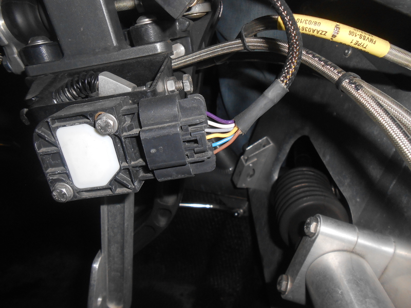
My multimeter have both - diode symbol and speaker - with is better to use?smokin wrote: ↑Thu Jan 24, 2019 3:44 pm Unplug the sensor connector and the cable end will look something like this:
Turn the dial on your multimeter to 20V DC
Cut off a length of paper clip or use a sewing pin and push it gently into the first of the 6 large terminal holes.
Turn ON ignition, hold the multimeter black cable against a good ground (bolt on the bracket securing steering rack should be good or battery negative terminal) and hold red cable against pin/paper clip. If it reads a voltage (probably 5v) then that is positive supply. Repeat this for each pin until both positives have been found
Turn OFF ignition, switch meter to continuity (diode symbol or speaker depending on your meter) and repeat the test for the other 4 pins. The 2 ground pins will show a reading close to zero or sound the buzzer depending on your meter.
The two pins that aren't power or ground are signal
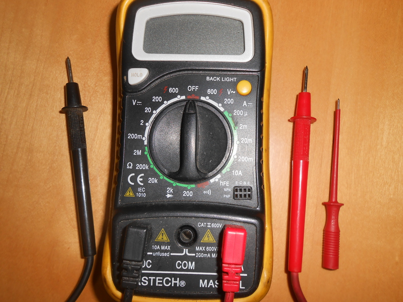
Actually, set it to the 200 between the diode and speaker. It will show resistence from zero to 200 and we're looking for a value close to zero so that will do nicely.Curves Junkie wrote: ↑Thu Jan 24, 2019 6:39 pm My multimeter have both - diode symbol and speaker - with is better to use?
No problem, happy to helpCurves Junkie wrote: ↑Thu Jan 24, 2019 6:39 pm WOW - you make my day. Thanks very much for your support.
Morning Henry,
It sounds great.
Users browsing this forum: No registered users and 1 guest